Now I’ve got the car back down on the ground, it’s time for a change of pace from the mechanical work – time to look at some of the electrics again!
I already did some work on the headlights and wiper motor, but now it’s time to get to work on the wiring loom itself. I’d pulled it out several years ago and dumped it in a box, but I knew it wasn’t going to be great. When the car was on the road I remember a lot of little niggles (such as the coolant light coming on when I put the handbrake on!), and when I pulled the loom out there was an unsettling amount of scotchloks and electrical tape.
So I was expecting this loom to at least need some patching up, and I was prepared to have to replace the whole lot. But, let’s see what we’ve got first!
Initial Inspection
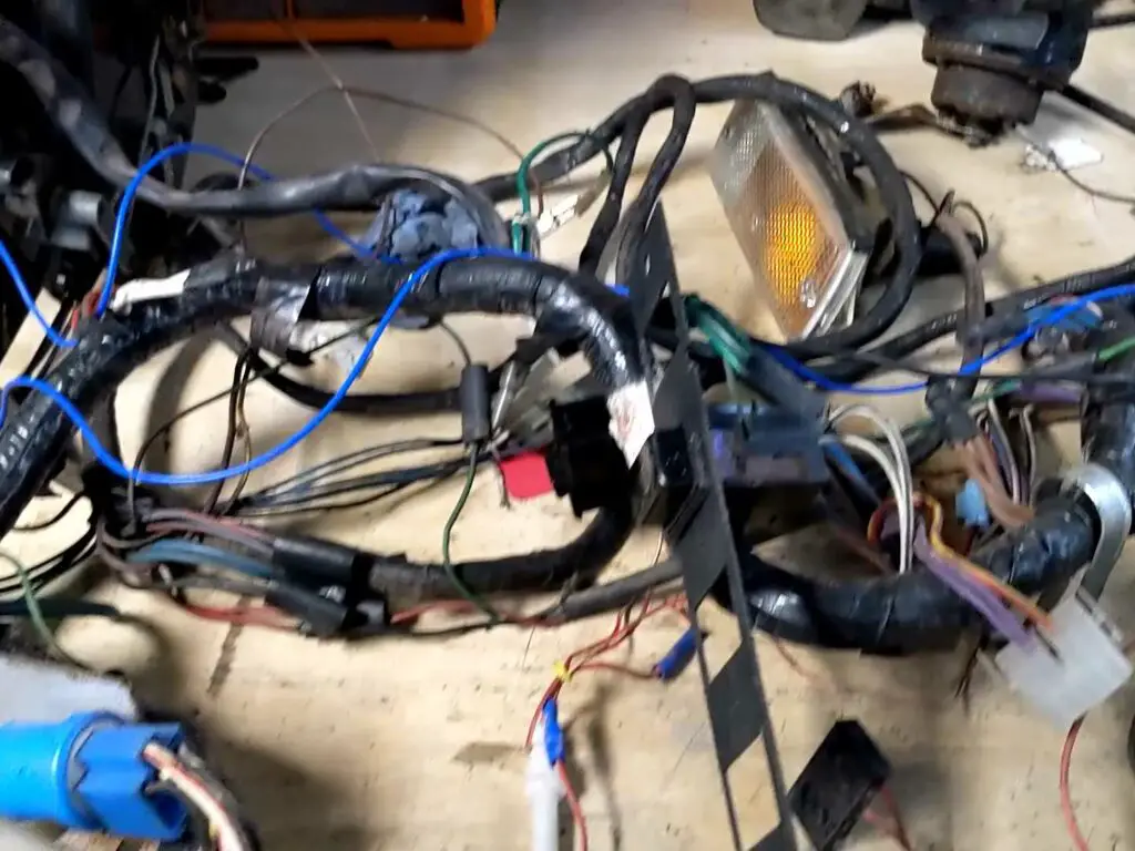
The first job was to pull everything out of the box and straighten it all out. Once it’s all laid out on the bench, there isn’t really all that much to it. The TR7 is still a fairly simple car electrically, without all the sensors and accessories you’d find in a modern car.
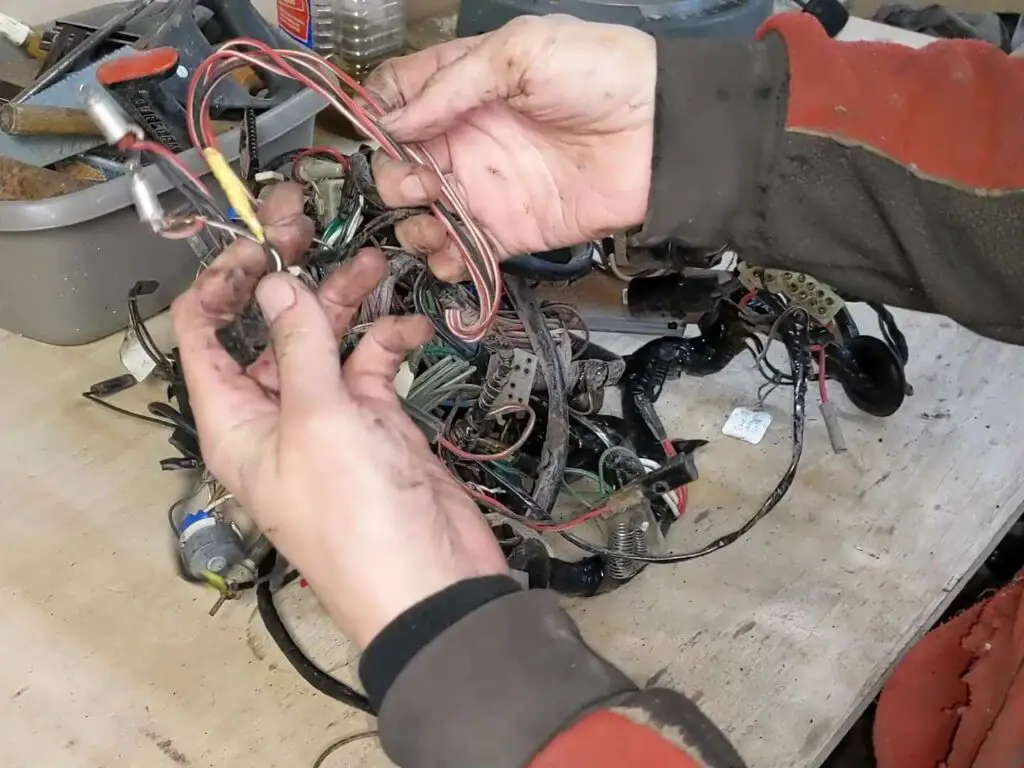
Testing the Components
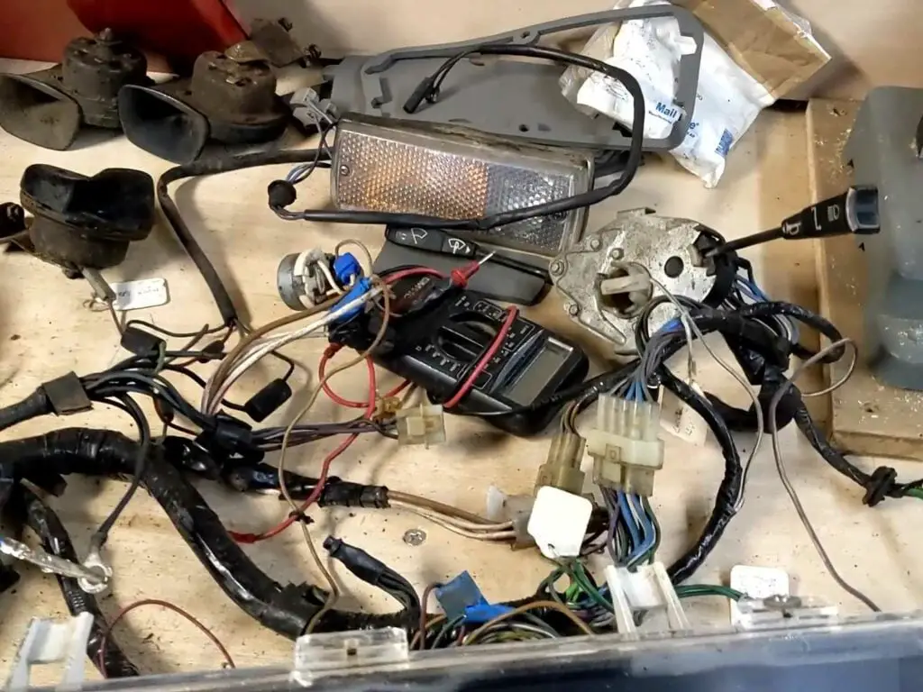
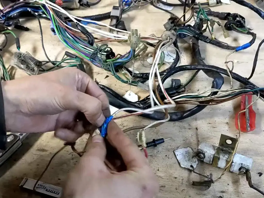
While I had the loom all laid out on the bench, I thought I might as well take the time to connect it all up, plug the components in and see what worked. There was a certain amount of lashing things together to get it all connected and it was definitely not the most stable setup, but it was good enough for testing purposes.
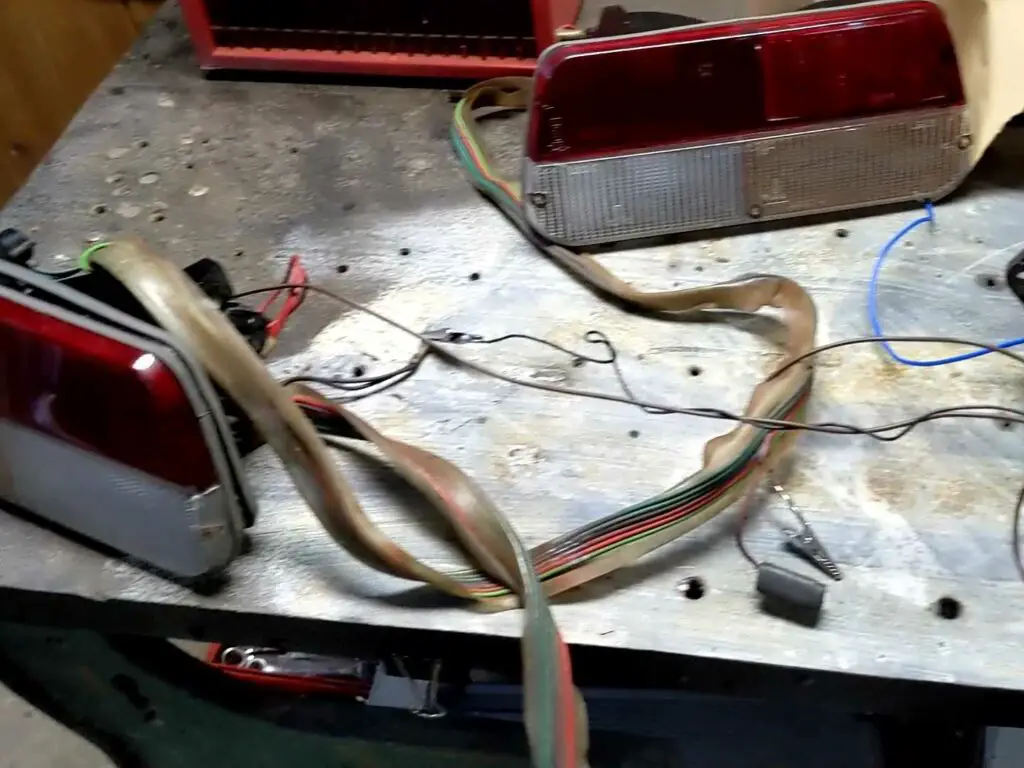
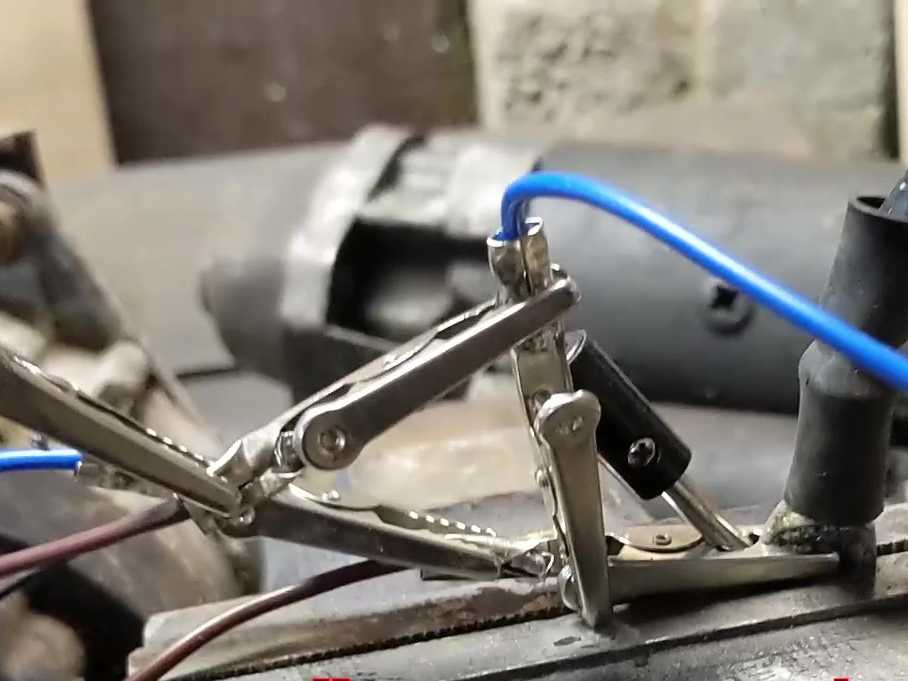
But, surprisingly, after a bit of fiddling about, it all seemed to work.
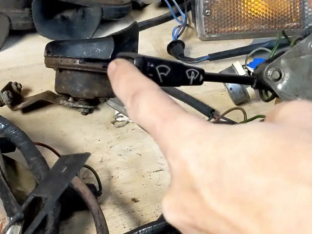
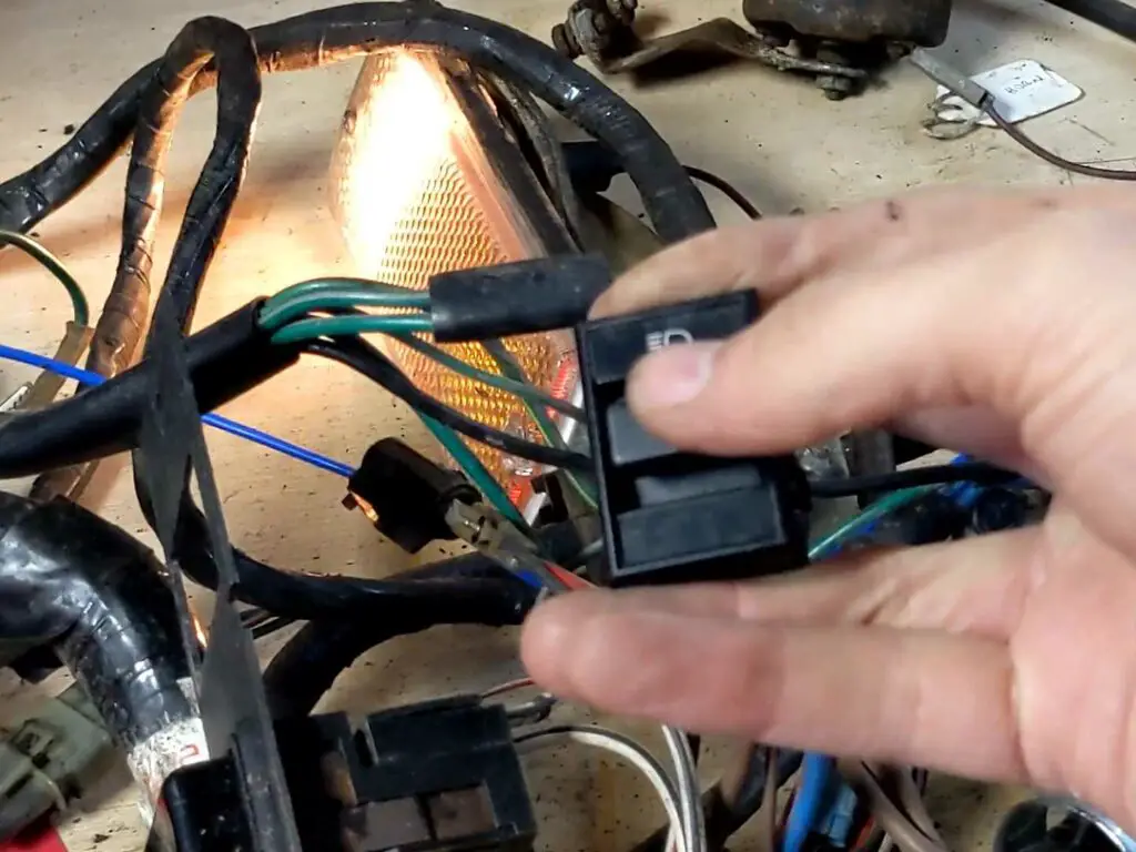
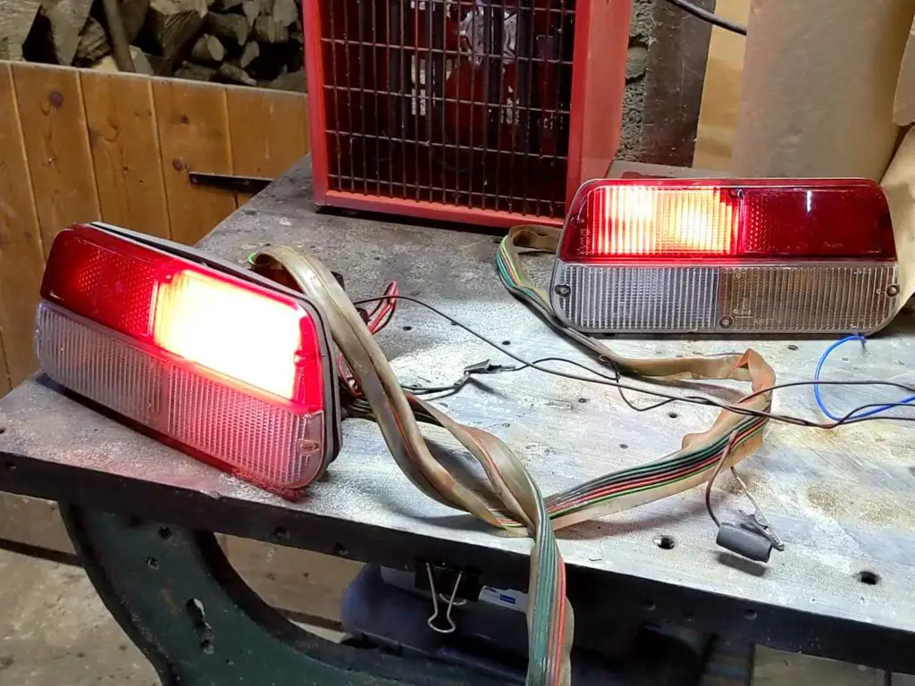
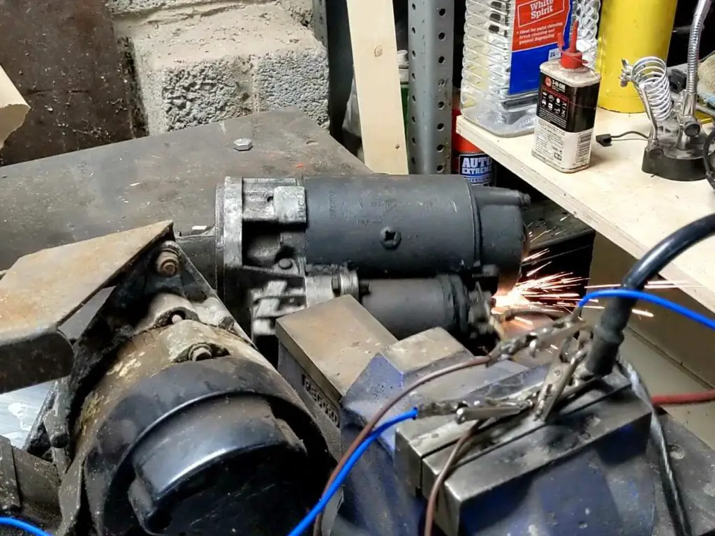
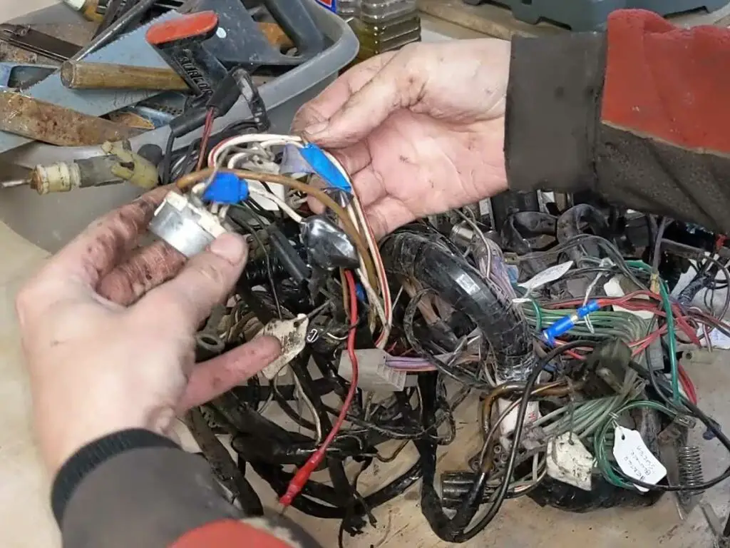
While there were more than a few intermittent connections and plenty of corroded wiring, the only real issues I had was with one of the indicators and one of the horns (the horn itself was dead, the wiring was okay). Even the starter worked okay, despite the poor wiring I had set up.
The only other issue was with the clock; these don’t tend to work that well anyway, but I’d taken the time a few years ago to repair this clock and modify it so it worked – so it was puzzling that it wasn’t working now.
Planning the New Loom
While everything worked surprisingly well, I decided in the end that there was too much going on here for it to be worth trying to repair it. The wiring is now 45 years old after all, and even the stuff that works isn’t in great shape.
So while my original plan was to cut out and replace the bad wiring and repair any bodges, by the time I’d done that I might as well just do the lot! This would also allow me to redesign the loom slightly and add in a few accessory items here and there without leaving random wires trailing all over the car.
New looms are actually available to buy, but they’re not cheap, plus I’d still need to do my own modifications, so I figured making my own would be the best option. Besides, it might be a fun experience!
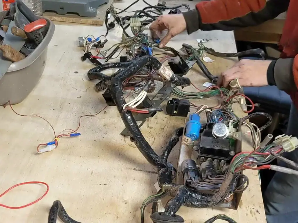
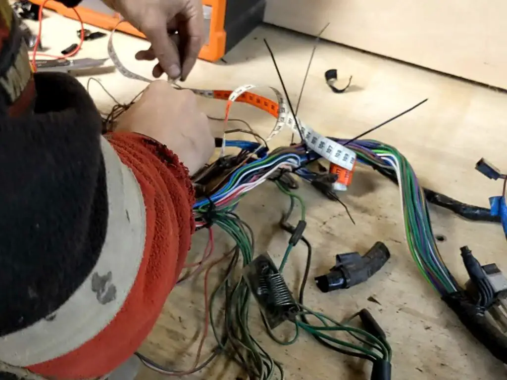
Rather than just randomly buying a bunch of wires, I decided the best place to start was to pull the old loom apart and measure everything up. This would allow me to buy just what I needed and (hopefully) not waste too much or find myself short halfway through putting it together.
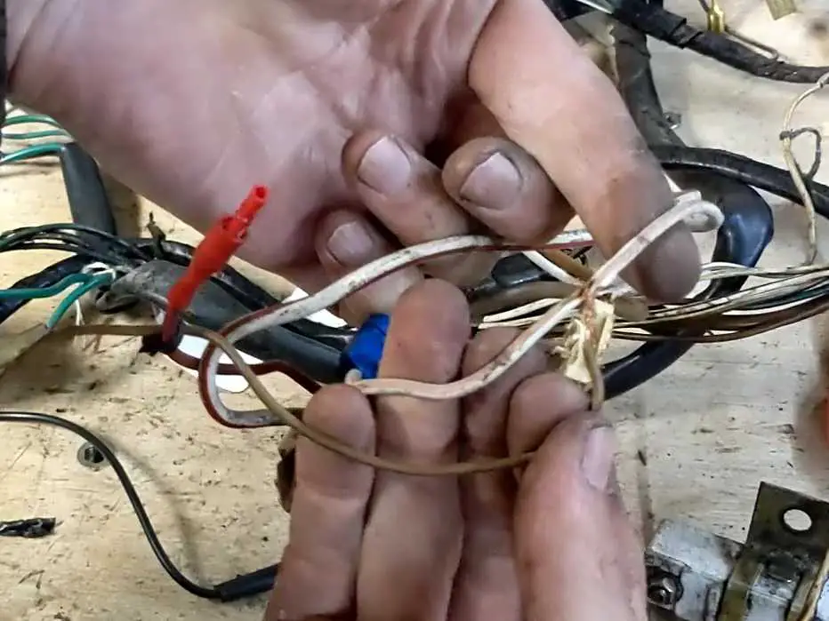
So I took all the components out again and started disconnecting everything, then carefully cut all the loom tape off to expose the wiring itself. To make sure I didn’t lose the shape of the loom and end up with a bunch of loose wires, I cable tied it all together at each junction point.
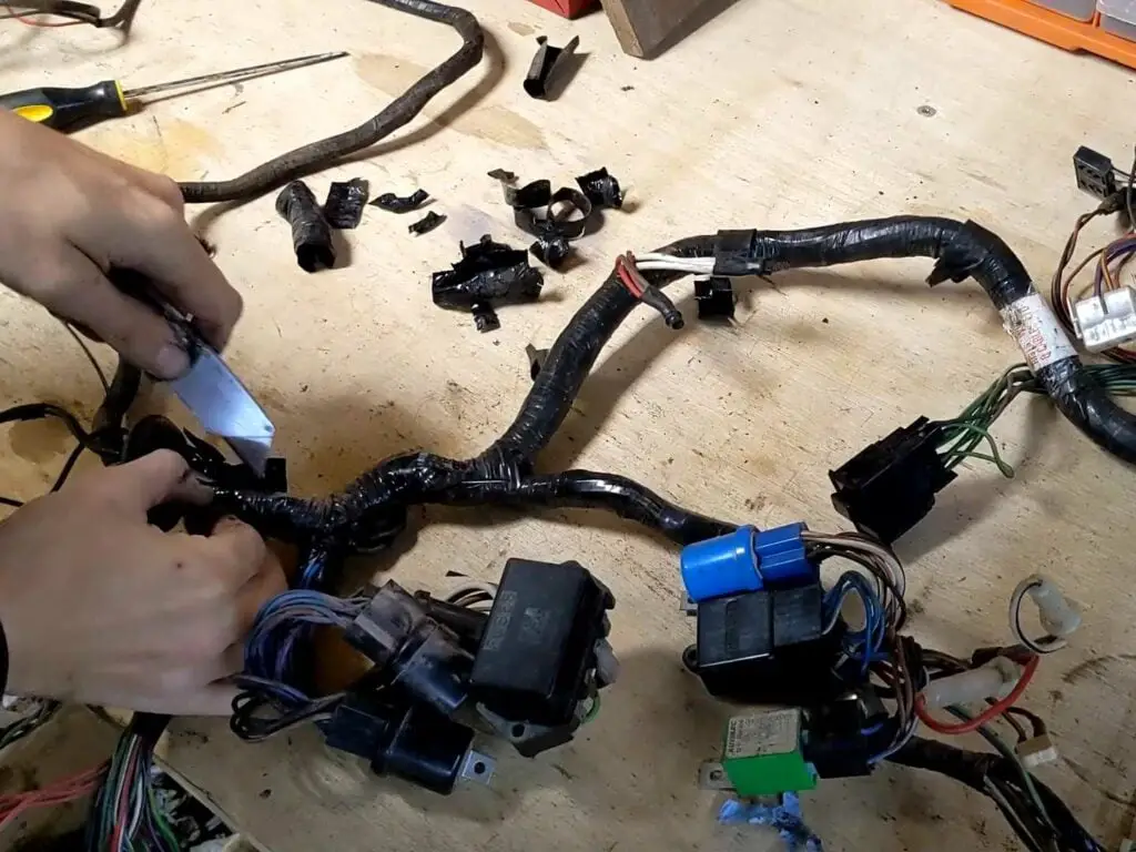
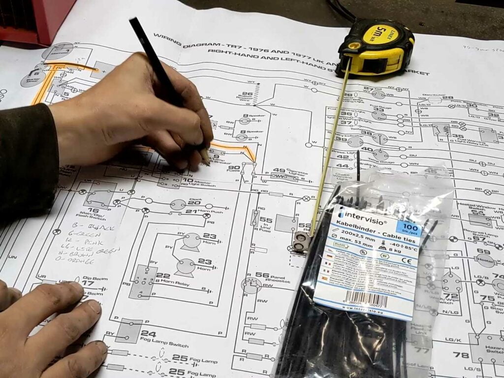
I wanted a wiring diagram I could work from; something I could print out at a decent size, and also edit where necessary.
There are a few PDF versions of the TR7 wiring loom around on the internet, but none of them were quite what I wanted; they were either broken up into subsystems or they were for the later, USA models. So I fired up Adobe Illustrator and made my own; firstly by copying the diagram from out of the workshop manual, and then using that as an overlay to draw the diagram in Illustrator.
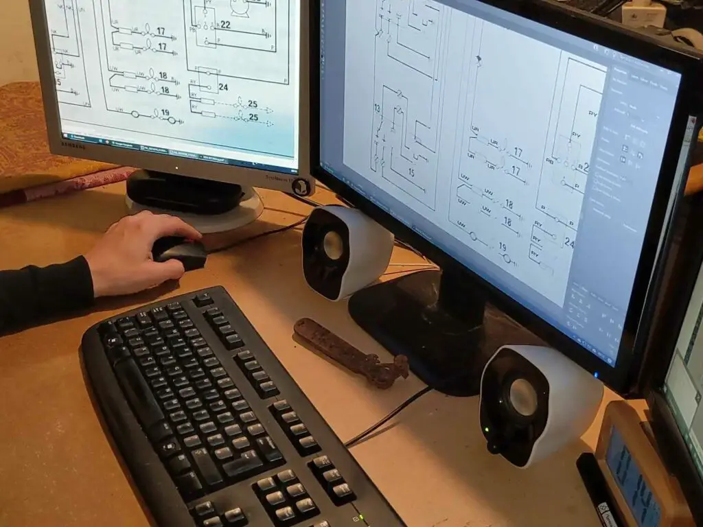
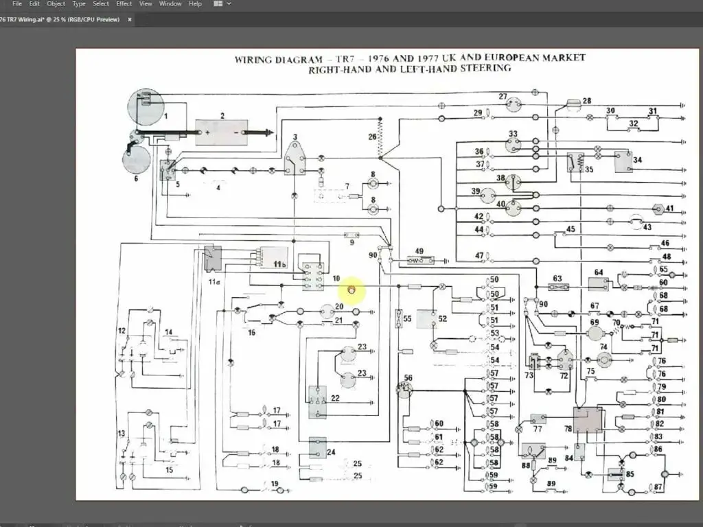
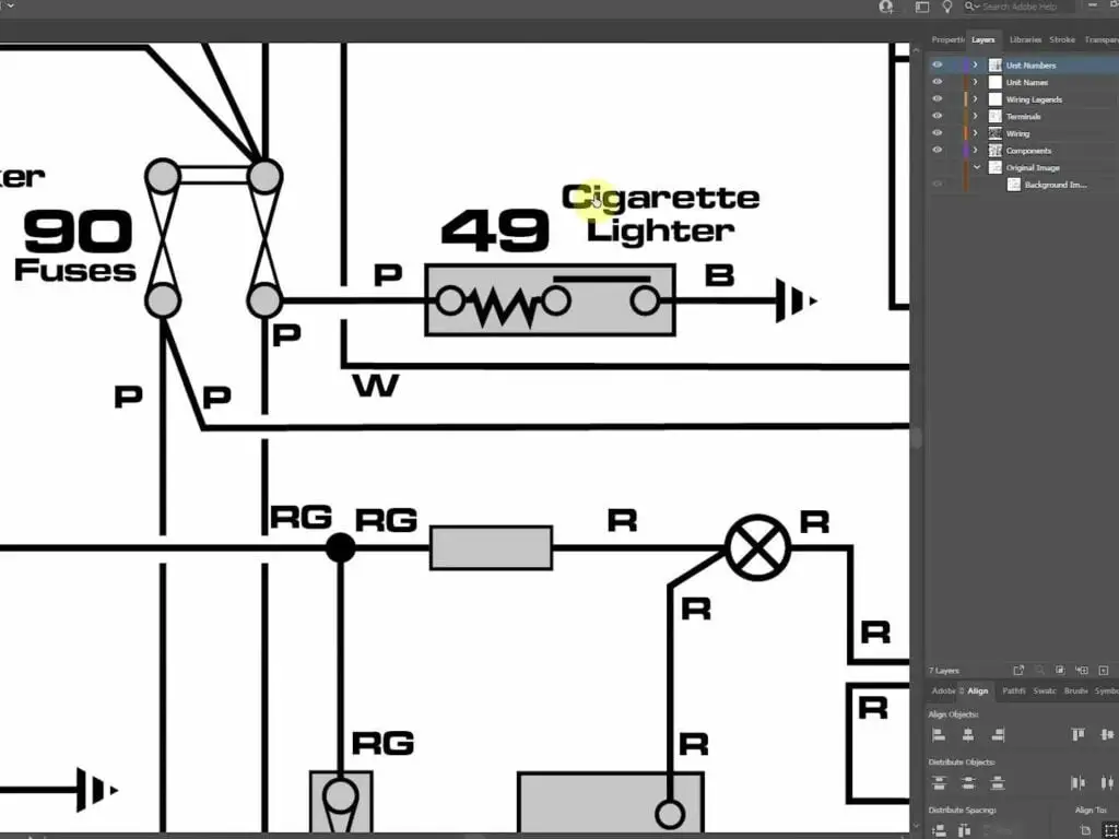
It took way more time than I’d care to admit, even to myself, but I’m quite happy with the end result: A fully scalable and editable wiring diagram specifically for the early models. Having this allowed me to print it out nice and big, rather than trying to work off the little A4 sized copy I started with.
If you fancy a copy for yourself, you can download it here:
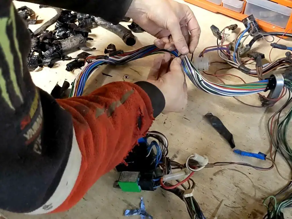
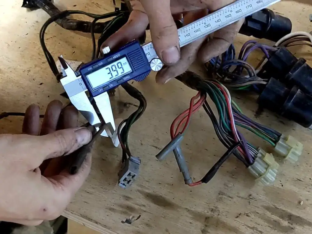
With that done I then set about measuring all the wires in the existing loom. It was a fairly long process, but I found it actually quite relaxing!
While I was pulling everything apart, I had a look under all that suspicious looking electrical tape to see what was going on. Turns out not much; just some slightly questionable wiring joints. Those will be replaced and repaired properly of course.
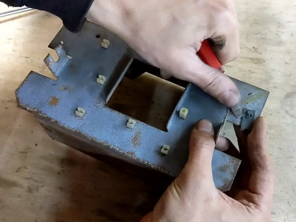
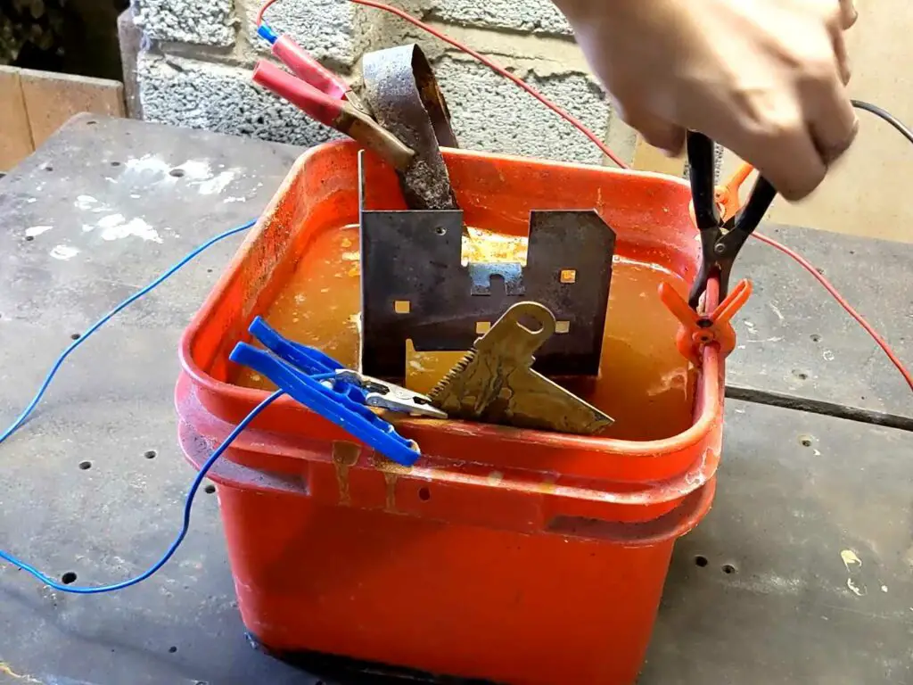
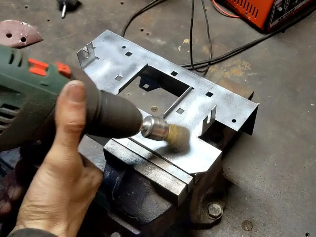
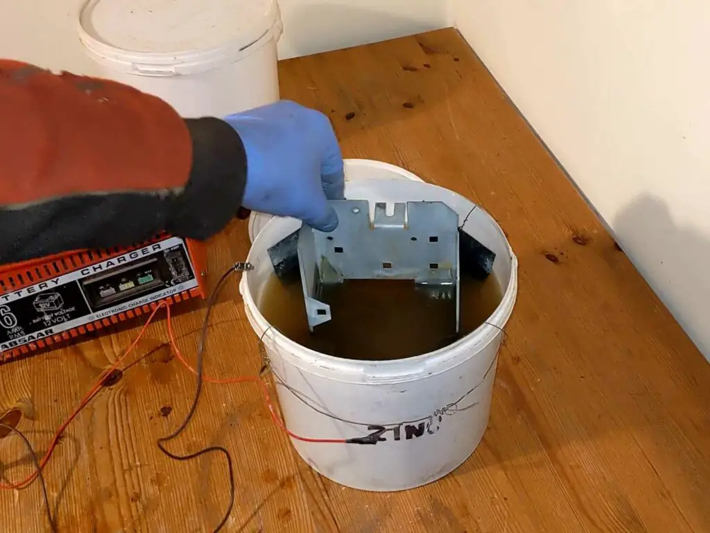
Cleaning and Replating the Fuse/Relay Holder
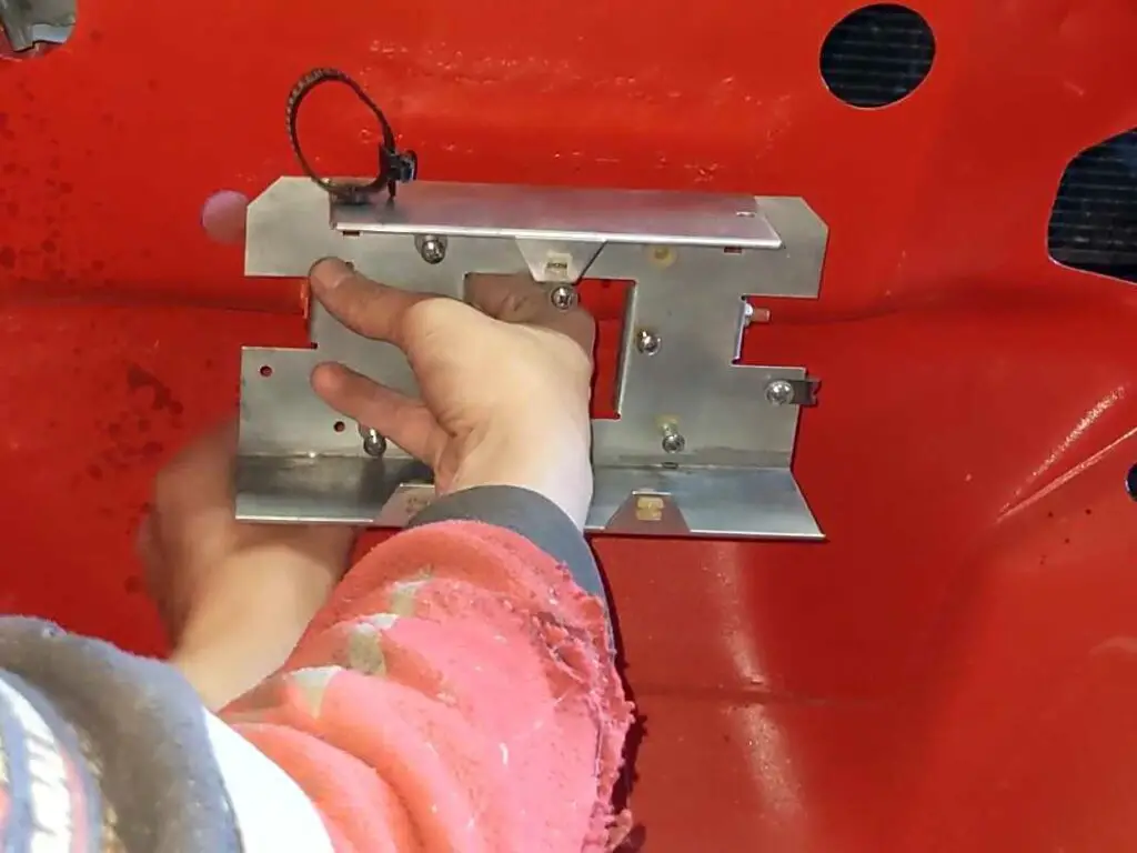
I decided to stop there and come back to this later on in the build, ideally when there are some components in the car I can actually fit all this to! Before I put it all away, though, I wanted to deal with the rusty old fuse and relay holder. So I took all the plastic parts off, cleaned and derusted it, then gave it some fresh zinc plating before fitting it back to the car.
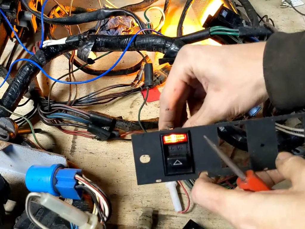
Fixing the Clock
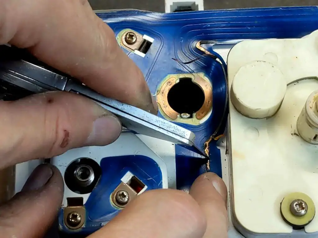
The last thing I wanted to tackle before putting the loom away was the clock – as mentioned before, this should be working, and indeed it worked fine when I took it out of the cluster and tested it. So that meant there was an issue with the circuit board.
A quick inspection revealed the culprit; the copper track on the circuit board had peeled up and broke. It’s a fairly common failure on these types of flexible boards, particularly after this many years.
These aren’t available new any more, and while I had a spare I could use, I elected to repair this one. It was only the one track that was broken, and a simple soldered repair should do the trick.
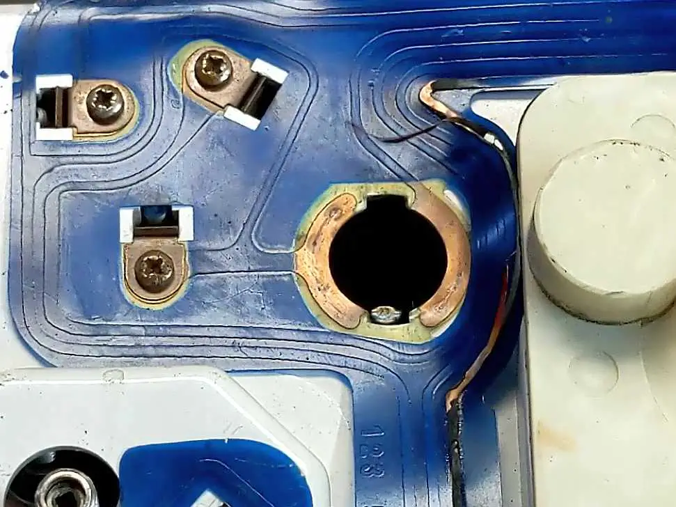
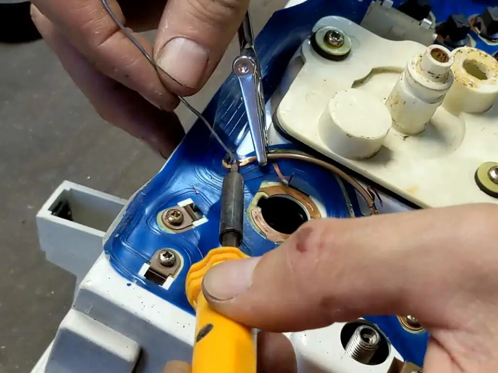
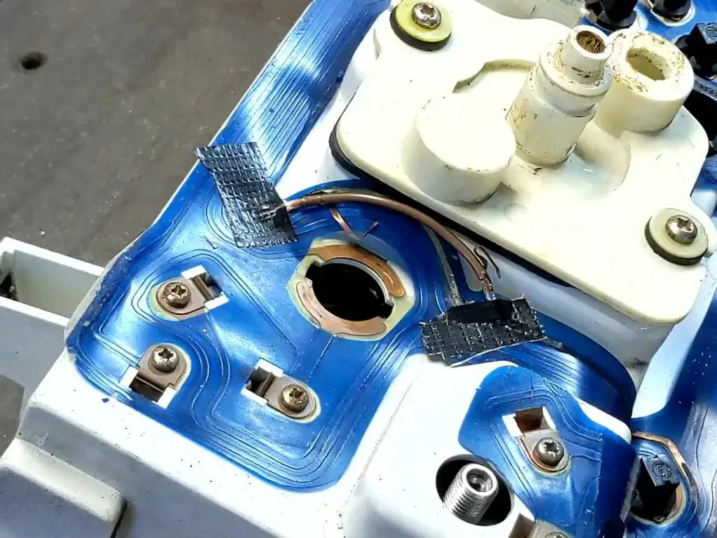
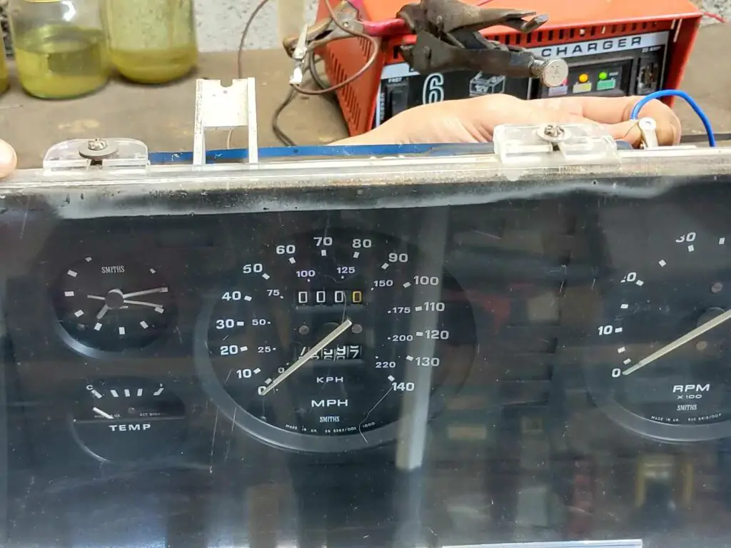
With the solder repair done, I tested the fascia and the clock now works as it should. Result!
I’ll be ordering new wires and terminals soon and making a start on the new loom, but I’ve got plenty to get on with before that!
The Video
As always, I got all this on video, and here it is. Enjoy!